In this part, the impedance of the whole board should be determined. Therefore I have carried out VNA measurements, recreated the layout in PCBSIM and derived an equivalent circuit to make simulations in SPICE.
The copper of the 3.3V supply can be modeled in PCBSIM:
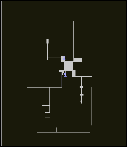
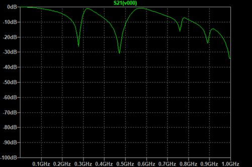
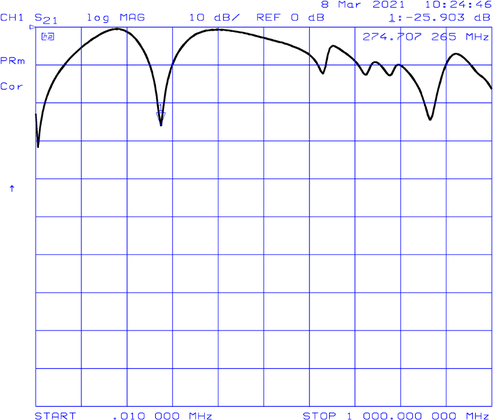
To compare it with measurements, I have chosen to simulate S21 parameter, connecting Ports 1 and 2 at the capacitor footprints near the uC.
The first picture is the simulated result:
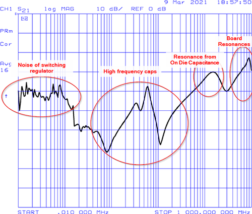
And the measured result:
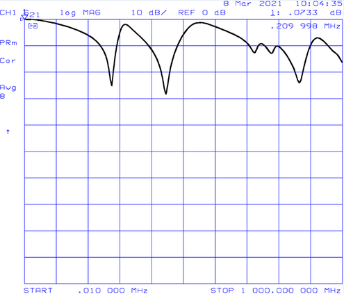
The capacitance of the copper alone is 39 pF at low frequencies.
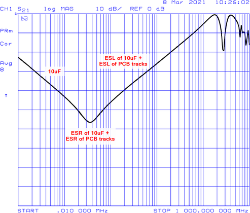
For the next measurement a 10 uF capacitor was added.
To get more details, the following diagram shows the same measurement with logarithmic horizontal scaling. The PDN is capacitive up to 400 kHz. As the 10 uF capacitor is placed at a distance, the resonance is at a quiet low frequency.
Next I have soldered the uC on the board and repeated the measurement.
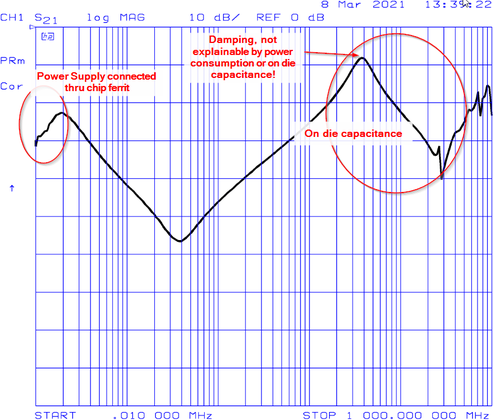
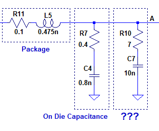
The capacitance of the uC seems to be 0,8 nF. If the chip is supplied with 3,3 V, the resonance at 40 MHz is damped.
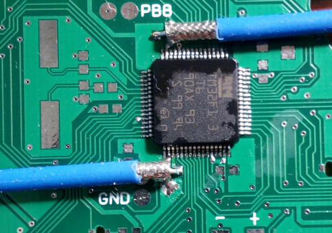
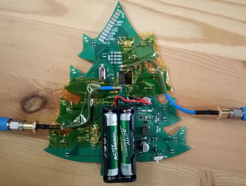
A picture of the soldered semirigid cables for the VNA measurement setup:
From the measurement an equivalent circuit of the uC was created. It is shown in the next picture. I have included something similar to an RC snubber with a resistance of 7 Ohm to model the damping of the resonance. It is an attempt to match the simulation results to the measurement.
The next picture shows a measurement of a fully populated board.
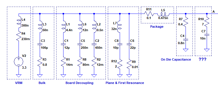
I have brought all the information together in a SPICE circuit.
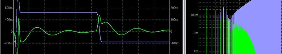
The impedance seen at the die is shown next:
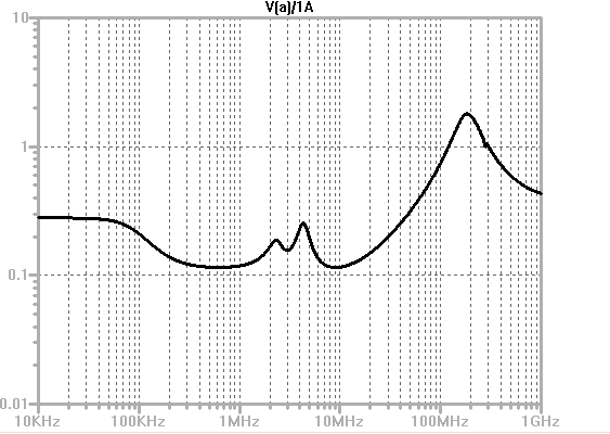
We will get an impedance of 0,3 Ohm up to 40 Mhz. Then there will be about 1 nH of inductivity resulting in a resonance at 200 MHz with a peak of about 2 Ohm. Due to the high inductivity the target impedance of part 2 cannot be met.
In the next part we will look on the effect of this impedance on the supply voltage in the time domain again.
Write a comment