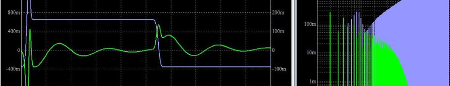
We have seen, that there will be some noise on the VCC net when the outputs of the uC are switching. The higher the impedance of the power distribution network, the greater the interference will be. But can this interference also cause radiation problems?
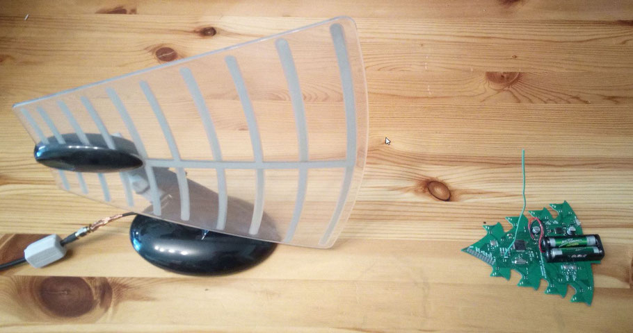
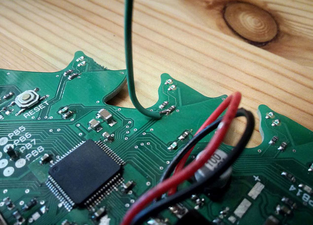
With printed circuit boards, cables are often responsible for the radiation. That is why I tried to recreate the worst case by soldering a wire to a GPIO that carries a static signal. In practice this could be a simple cable connected to a status LED or a switch somewhere in the device. One would not assume that a static signal can cause problems.
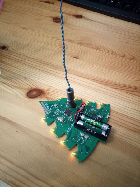
The picture below shows the arrangement. The cable in combination with the GND plane builds a nearly perfect monopol antenna. A monopol antenna has a theoretical lossless input impedance of 36,5 Ohm. If we assume that 5 µA of common mode current can exceed radiation limits, the voltage must be less than 0,18 mV for a specific frequency !!
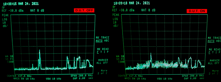
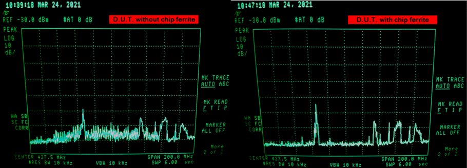
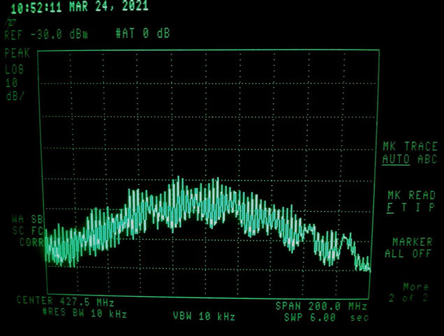
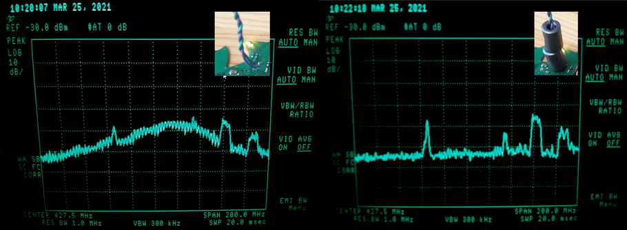
The uC is toggling all GPIOs of one port as fast as possible. The next picture on the left side shows the spectrum analyzer measurement with the uC turned off to see the background noise. On the right side the uC was powered on. The frequency span is adjusted to the length of the attached cable. It radiates maximally in the range of 427 MHz.
If the antenna is only 15 cm away from the source, you can just detect interference.
A common mitigation technique is to add a chip ferrite where the cable exits the board. I have soldered in a chip ferrite of the type BLM21PG331SN1D and repeated the measurement.
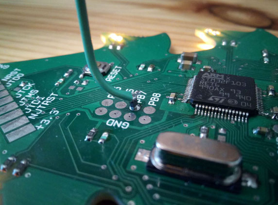
With the chip ferrite the radiated interference is not visible any more. With this experiment I want to show that it is important to filter every signal that is leaving the board, not only highspeed signals.
If a signal with fast flanks is connected directly to a cable without a possibility where the return current flows the radiation is clearly horrible. In the next setting the short cable with about 17 cm in length is connected to one of the fast switching GPIO pins.
This setup will likely fail radiation compliance tests.
What if we give the return current a chance to flow near the signal wire? I have added another cable connected to GND and twisted with the obvious monopol antenna. Does it help to reduce radiation?
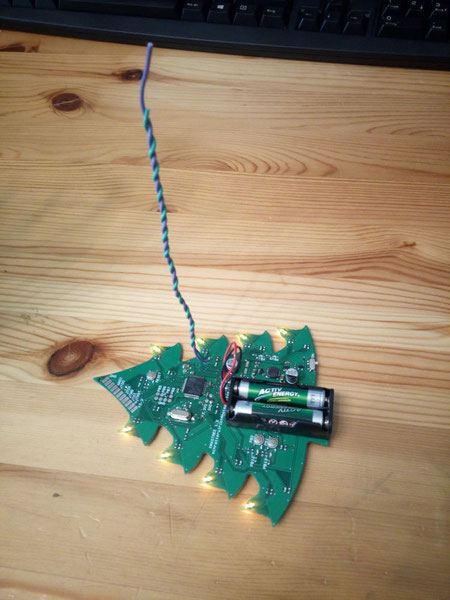
And the answer is... No - It does not reduce the radiation remarkably! It still suffers from common mode currents. The symmetrical structure of twisted pair cables would also require balanced signals to minimize radiation.

A common mode choke or ferrite bead can balance the signals without attenuating the differential data.
And as we can see, the addition of ferrite cores attenuates the radiation. Of course the GND at the end of the GND cable is not at the PCB GND level any more. Instead it will be at half the signal amplitude even if hard to measure. The ferrites make this possible.
But then how can FFC cables with hispeed signals be laid across the entire width of a TV set, for example?
First with differential signals and common mode chokes.
And if single ended signals are necessary, you have to provide the same asymmetry between signals and GND as on the printed circuit board. You can see this in TVs when FFC cables are taped to the metal housing over the entire length.
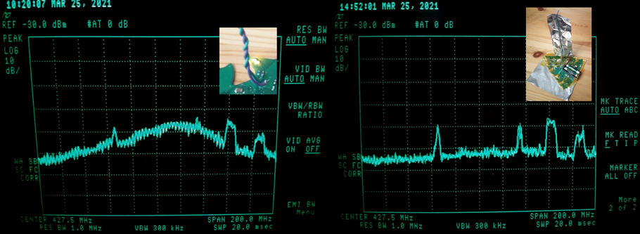
I can replicate this for an experiment with aluminum foil.
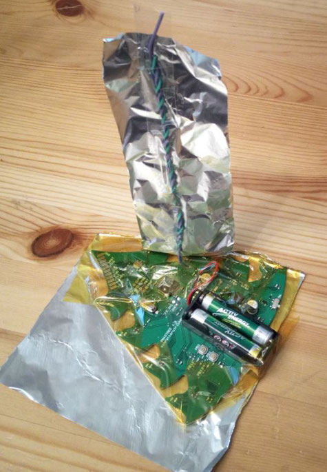
The radiation has almost disappeared. Note that the aluminum foil is not connected to GND. It is only capacitively coupled. Now the common mode currents of the PCB has become differential currents between PCB and aluminium foil.
Single ended signals tend to create common mode currents, if they run over unshielded cables. You need appropriate countermeasures to minimize the radiation.
Write a comment