EMC compatible circuit board design
EMC compatible circuit board design · 10. September 2022
Ground bounce is often suspected to generate problems like EM radiation issues and measurement errors. In this context, fast digital lines are often mentioned to generate ground bounce on PCBs. I wanted to measure the voltage drop on a ground plane excited by the return current of a microstrip signal.
EMC compatible circuit board design · 19. December 2021
I have simulated and measured the voltage noise of a buck converter at its input side in the previous post. This time I have sodlered a wire on different positions to create radiation from it.
EMC compatible circuit board design · 30. November 2021
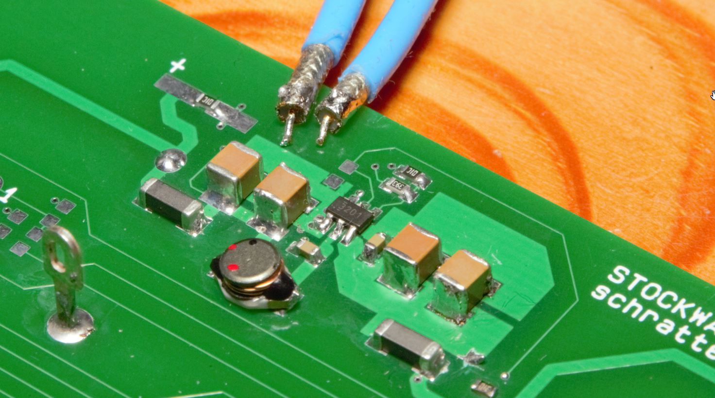
With my latest project, I wanted to check the noise generated by a buck converter on its input.
EMC compatible circuit board design · 12. November 2021
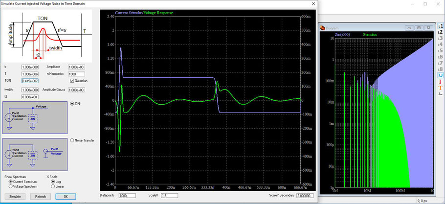
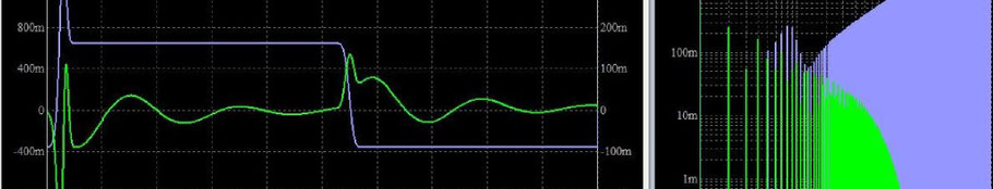
In the new version of PCB SIM it is possible to stimulate the impedance with a trapezoidal waveform in the time domain. Therefore the waveform is generated with a fourier series and multiplied with the impedance in the frequency domain. The resulting spectrum is transferred back into the time domain. It can give valuable insight in the bandwidth requirements of switched signals.
EMC compatible circuit board design · 07. June 2021
Die GND Plane hat auf dieser Experimentierplatine eine U-Form. Über den Schlitz entsteht eine kapazitive Kopplung der beiden GND-Hälften zueinander. In Kombination mit der Induktivität bzw. der räumlichen Ausdehnung zeigt diese Struktur höchstwahrscheinlich Resonanzen, an denen die Abstrahlung zunimmt.
EMC compatible circuit board design · 19. April 2021
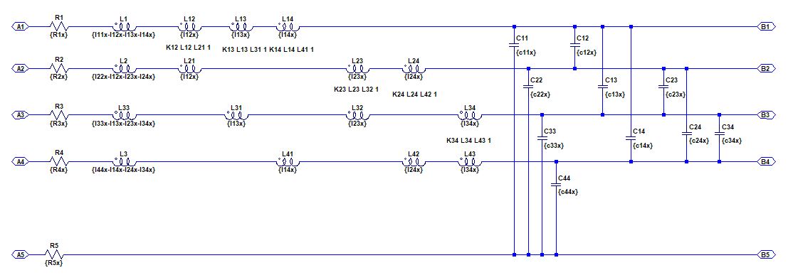
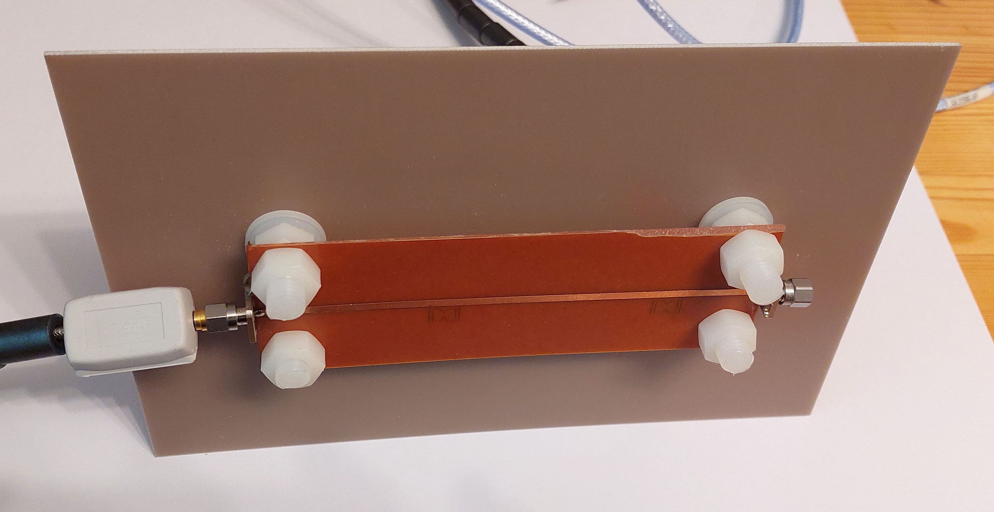
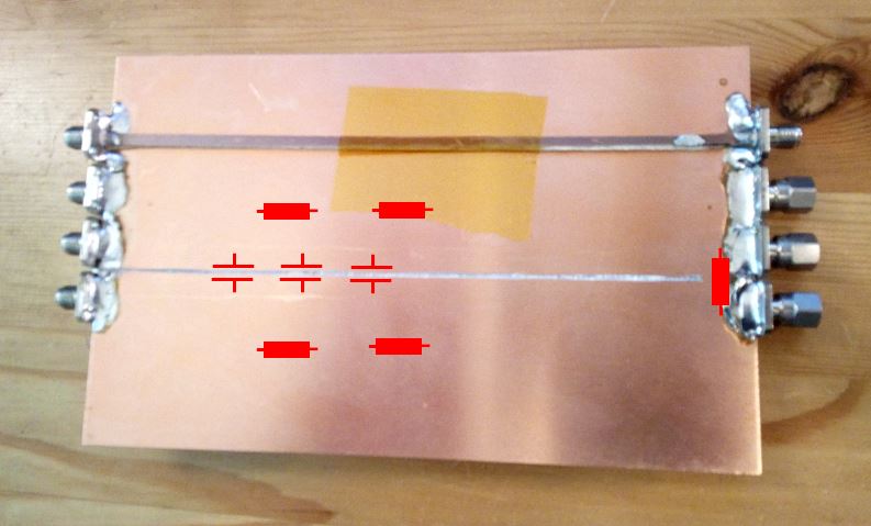
In Part 1 wurde das Übersprechen auf einer Testleiterplatte mit 3 parallel verlaufenden Microstrip-Leitern messtechnisch erfasst. Für DC Signale konnte das Übersprechen durch den ohmschen Widerstand der GND-Plane nachgebildet werden. Dieser Teil stellt ein Simulationsmodell vor, dass das Übersprechen auch im Bereich der L- und C-Kopplung nachbilden kann. Dazu wurde in einem kommerziellen Field Solver die Kapazitätsmatrix und Induktivitätsmatrix der Leiteranordnung bestimmt. Eine...
EMC compatible circuit board design · 13. April 2021
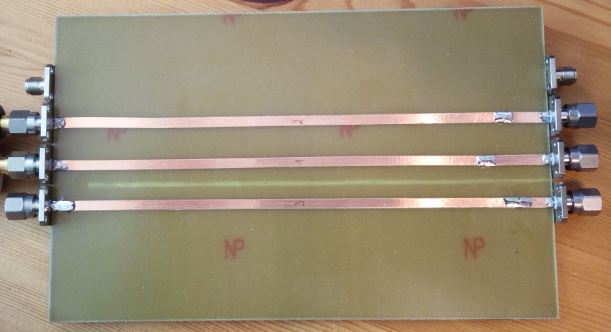
Es wurde eine simple Testleiterplatte erstellt, mit der das Übersprechen von parallel laufenden Microstrip-Leitungen untersucht werden kann. Da es immer wieder zu Diskussionen um Schlitze in Masselagen bzw. Sternpunkte von Masselagen kommt, soll dieser Test dazu dienen, eine mögliche Reduktion des Übersprechens durch eine getrennte Masselage aufzuzeigen.
EMC compatible circuit board design · 24. March 2021
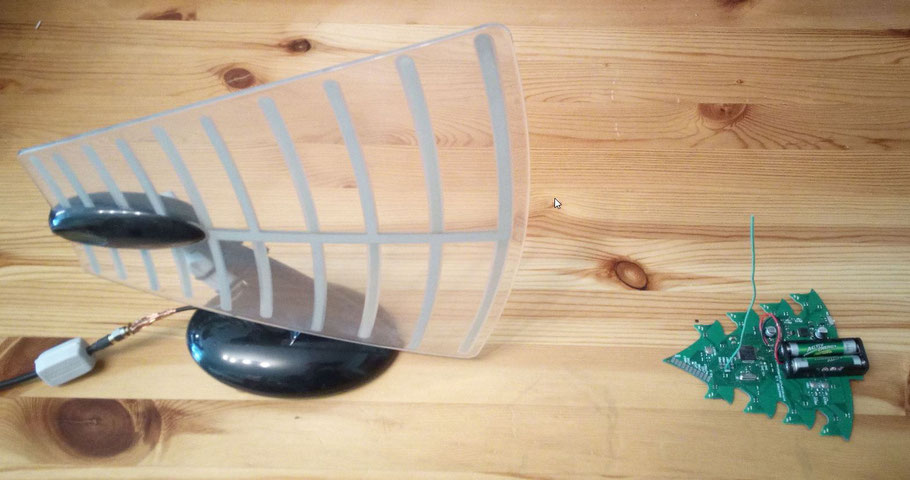
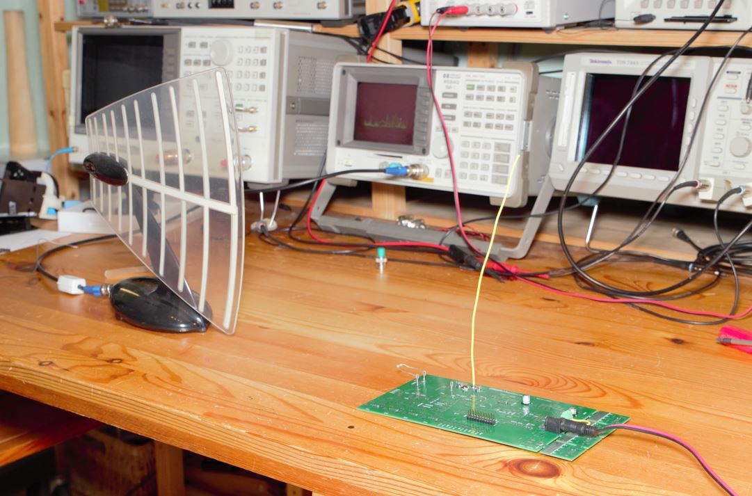
We have seen, that there will be some noise on the VCC net when the outputs of the uC are switching. The higher the impedance of the power distribution network, the greater the interference will be. But can this interference also cause radiation problems? With printed circuit boards, cables are often responsible for the radiation. That is why I tried to recreate the worst case by soldering a wire to a GPIO that carries a static signal. In practice this could be a simple cable connected to a...
EMC compatible circuit board design · 23. March 2021
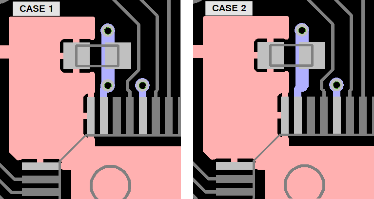
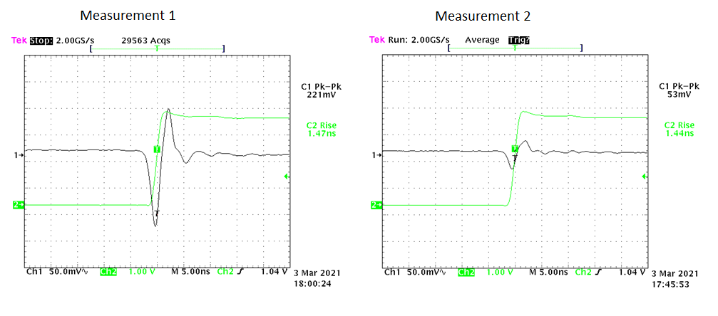
I often see the recommendation to sequence the placement of bypass caps in the order via - capacitor - pin. As this is not the way I do it, this part investigates the effect of not following this sequence. I usually place a via as close as possible to the GND pin of the IC. If space permits, I place 2 vias at each PWR and GND pin. To see if there is a measureable difference when omitting the via closest to the GND pin I have drilled them away on the bottom side.
EMC compatible circuit board design · 22. March 2021
In this part, I want to show the noise voltage on VCC when the GPIOs of the STM32 uC are switching. To directly measure the voltage on the die of the chip, an additional GPIO is held at high level and the probe is connected to this GPIO.