This article should investigate the properties of a simple "Blinky" project.
I have chosen this example, because it is simple enough to create an equivalent circuit in SPICE. Therefore we can get a better understanding of the power distribution network of a simple uC project.
In this part I want to create an equivalent circuit of the load - 16 LEDs. In combination with the measured waveform I want to simulate the currents, that the uC has to deliver on its GPIOs.
I have measured the signal at R1 coming from the uC.
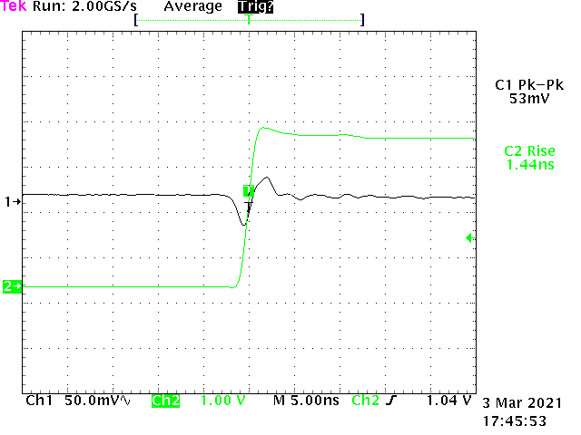
CH2 shows the signal with a risetime of 1,44 ns. This is with the fastest GPIO settings of the uC. Normally I would select the slowest setting, for driving LEDs, but in this case I want to challenge the stability of the voltage rail. From the voltage drop of the series resistor I can calculate a current of 4 mA when the LED is on.
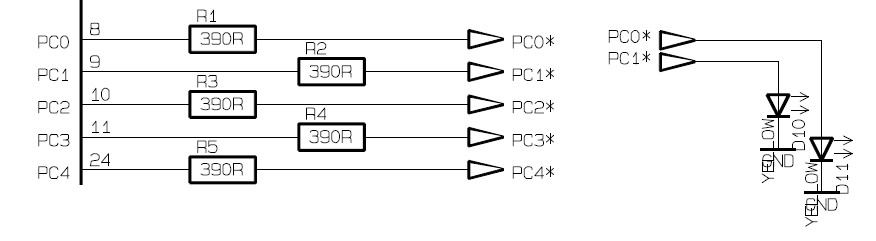
I have created an equivalent circuit, combining all 16 I/O ports:
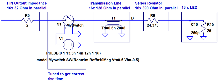
The internal resistance of 32 Ohm is extracted from an IBIS simulation not shown here. The switch is tuned in such a way, that the simulated output waveform matches the measured one. The signals are routed on the PCB as microstrip with 0,15 mm width. On a two sided 1,6 mm PCB this corresponds to 128 Ohm transmission line impedance. For this simulation it is sufficient to model the LED with its intrinsic capacitance and an equivalent resistance when turned on.
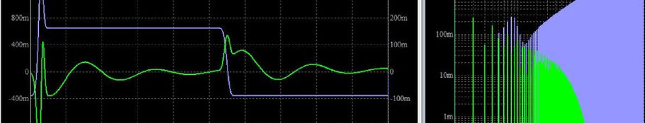
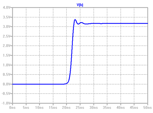
The simulation gives following result:
This is the voltage waveform with 1,4 ns rise time.
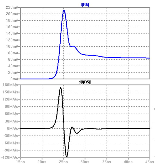
The current peaks at 210 mA. If the round trip delay of the microstrip lines were longer than the rise time of the signal, the maximum current would be defined by their impedance.
An interesting figure is how fast the current changes. At the bottom of the next diagram the derivative of I(R5) is shown.
We can read out a maximum di/dt of 175 ma/ns.
The FFT shows, that the frequency content reaches up to 400 MHz.
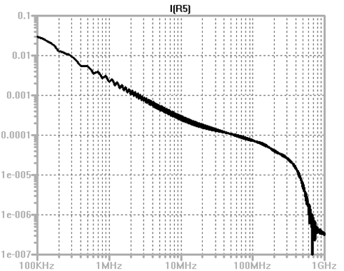
We see, that the PDN has to deliver max. 210 mA up to frequencies of at least 400 Mhz.
The next article shows how the PDN has to be laid out to achieve these figures.
Write a comment